
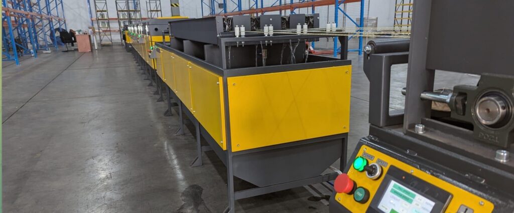
The building looks right. The rent fits the budget. There is enough floor area for the production line. Then someone asks how a bundle of finished bars will turn past the last column and reach the loading door.
That is a question worth answering before you sign the lease.
A practical GFRP rebar factory layout needs space for the full operation: receiving materials, feeding the line, running production, checking product quality, packaging orders and loading trucks. Electrical supply, cooling, compressed air and ventilation must be matched to the selected equipment and materials.
At Composite-Tech, we recommend developing the equipment layout and the building plan together. A machine drawing tells you where the equipment sits. The factory plan must also show how people and materials move around it.
Contents
Start with the bars you plan to ship
Before drawing the production area, define the finished product. Record the bar sizes, cut lengths, packaging method and expected stock levels. Include the products you expect to make first and any realistic expansion plans.
A plant shipping straight bars has different handling needs from one shipping suitable products in coils. Coiling must be confirmed for the specific product and equipment configuration; it should not be assumed for every diameter. Mesh sheets and bent elements also need their own handling and storage arrangements.
For straight bars, follow one finished bundle through the building on paper. Where does it leave the cutting area? Where is it inspected and labeled? How is it lifted, stored and taken outside? Check the bundle’s full length at doors and changes of direction.
Include the truck yard in that exercise. A generous loading door is useful only if the vehicle can approach it and the handling equipment can work around the load.
How much space does a GFRP rebar factory need?
The answer depends on the selected line, its service clearances, the finished bar lengths and the inventory you intend to hold. A single square-foot figure cannot describe all of those requirements.
For example, a 40-by-150-foot building and a 60-by-100-foot building both provide 6,000 square feet. Their usable straight runs are different, even before accounting for columns, offices and doors. Neither set of dimensions is a recommended factory size; the example simply shows why total area is an incomplete selection criterion.
Request a dimensioned layout for the complete configuration, including the creel, processing sections, cooling, pulling, cutting and any collection or winding equipment. Mark the space needed to load materials, open guards, remove components and service the line.
Then add storage, inspection, packing and circulation areas. Confirm clear height at the lowest obstruction, rather than relying only on the advertised building height. Doors, beams, overhead services and any planned lifting equipment can affect the usable space.
Our GFRP rebar production equipment page introduces the line range. A project layout should be based on the configuration proposed for your products.
Arrange the factory around material flow
A useful first draft follows the journey from incoming raw materials to dispatched orders. Straightforward routes can reduce unnecessary handling, but the best arrangement depends on the building. A shared receiving and shipping door, for example, needs a plan for staging deliveries without obstructing production.
| Factory area | What the layout should allow | Question to resolve |
|---|---|---|
| Receiving and raw material storage | Unloading, identification, inspection and storage under supplier-specified conditions. | Can a delivery be unloaded without blocking the line or finished orders? |
| Creel and material preparation | Access for replenishment, material handling and the selected preparation process. | Can operators load and service this area with the equipment in its final position? |
| Production line | The full equipment arrangement, utility connections and operating and maintenance access. | Are clearances based on the supplier’s drawing and local design review? |
| Inspection and batch holding | Sampling, identification and separation of material awaiting a release decision. | How will staff distinguish released product from material still being checked? |
| Packaging and finished stock | Bundling or other specified packaging, labeling and supported storage. | Can the largest planned product be handled without crossing busy work areas? |
| Dispatch | Order staging, loading access and truck movement. | Can an order leave while production and receiving continue? |
Use this as a planning sequence, not a mandatory room arrangement. Some activities may share a suitably designed area. Others may need separation because of the materials, traffic or quality procedures involved.
The Composite-Tech guide to the GFRP rebar manufacturing process explains the production stages behind these layout decisions.
Check electrical capacity against the complete equipment list
“The building has three-phase power” is a starting point. It does not establish whether the supply matches the machine or whether sufficient capacity is available.
Ask the equipment supplier to specify voltage, phase, frequency, connected load and the information required for electrical installation. Have a qualified local electrical professional compare those requirements with the building’s available service and distribution system.
Keep connected load separate from expected operating consumption. A quoted average power figure used for production costing is not a basis for selecting feeders or protective devices. Startup conditions and simultaneous loads also need to be considered in the installation design.
Include equipment supplied locally: compressors, cooling equipment, extraction, lighting, HVAC and handling equipment where relevant. Record which items are included in the line quotation and which belong in the factory preparation budget.
Resolve any required equipment documentation, inspection or evaluation with the responsible local parties before delivery. If the proposed electrical supply changes during the building search, send that change back to the machine supplier.
Plan cooling as a complete system
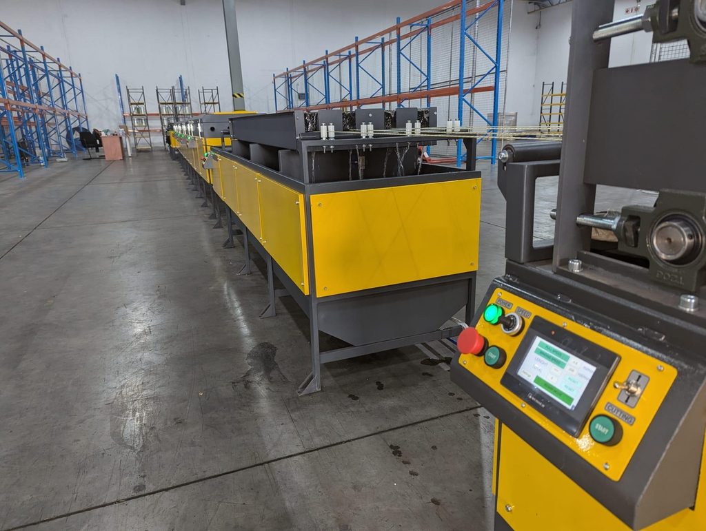
A cooling section on the production drawing still needs a defined source of cooling. Depending on the configuration, the project may include water circulation, a tank, pumps, filtration, a heat exchanger or a chiller. Confirm the actual arrangement rather than buying accessories from a generic list.
Request the required flow, pressure, inlet temperature range and water quality, together with the heat load or equipment selection information. Identify where the heat will be released. Equipment selected for one ambient condition may need a different arrangement in a hotter location.
There is also an important distinction between circulating water flow and water consumption. They are not interchangeable figures. Even when water recirculates, the facility plan should address maintenance, replenishment and how any necessary draining will be handled.
Show the cooling equipment and service access on the layout. Leaving those items until installation can consume space that was intended for stock or movement around the line.
Specify compressed air at the point of use
If the chosen configuration uses pneumatic equipment, obtain its operating pressure, air demand and air quality requirements. Compressor motor power alone does not establish whether the system can supply the line.
Ask whether the stated demand is average or peak, and whether several devices operate at once. Confirm any required filtration or drying with the supplier. An air dryer should be selected from the actual requirement, not assumed to be included with the compressor.
The pipe route, treatment equipment and other air users affect what reaches the production line. Include them in the design, along with service access, noise considerations and heat released by the compressor.
Use the selected materials to plan storage and ventilation
Obtain the current safety data sheets and technical data sheets for the resin system and other materials you intend to use. These documents serve different purposes: safe handling information and process or storage recommendations both matter.
For the safety data sheet, Section 7 addresses handling and storage, while Section 8 addresses exposure controls and personal protection. OSHA’s guide to safety data sheets explains those sections. Use the information for the actual products, including any relevant incompatibilities, when developing the facility plan.
Have ventilation needs assessed for the work being performed, including material preparation and any cutting or finishing operations. A general building fan is not a substitute for evaluating the sources that need control. OSHA describes ventilation as an engineering control for workplace air quality; the appropriate design is process-specific.
Roving storage also needs attention. Follow the material supplier’s recommendations, protect stock from damage and keep identification readable. Make it practical to use the intended batch and move replenishment material to the creel without disrupting adjacent work.
During building selection, have the proposed use, material inventory and utility alterations reviewed by the relevant local professionals and authorities. This guide is a planning aid, not an installation design or a determination of local permitting requirements.
Give quality control a physical place in the factory
Quality procedures are easier to follow when the layout makes room for them. Decide where samples are taken, where they are identified and stored, and where product waits if a check is still outstanding.
A new plant may use an external laboratory for certain tests. It still needs a practical way to collect samples, maintain records and link finished product to production batches. The on-site equipment and workspace should follow the quality plan agreed for the product and its customers.
A clearly identified holding area helps prevent material awaiting review from being packed into a released order. The area does not have to be elaborate, but its purpose must remain clear when the factory becomes busy.
Allow for maintenance and the next stage of production
Look beyond the operator’s normal working position. Can a technician reach the cooling system? Can a component be removed without dismantling a storage rack? Is there a practical place to keep spare parts and tools?
Check those questions on the equipment drawing before routing utilities or installing permanent storage. Floor condition, equipment support and any anchoring requirements also belong in the installation review.
If later expansion is realistic, show its location now. A second rebar line may affect electrical capacity, cooling and dispatch. GFRP mesh production and bent elements manufacturing introduce different product shapes and handling tasks. Reserve space only after understanding what those operations would require.
Bring these documents to the layout discussion
A useful first discussion can begin with a measured floor plan and a short product list. Include the clear internal dimensions, column positions, doors, usable height and available electrical supply. Photos are helpful, particularly where a drawing does not show an obstruction or a difficult access route.
Add your intended bar sizes, finished lengths, target output, storage expectations and loading method. Mark what is confirmed and what is still an estimate. If the building is not yet selected, the same information can become a checklist for comparing properties.
Before installation, agree who supplies each utility and where the supplier’s responsibility ends. Keep the approved layout and utility schedule under revision control so the electrician, cooling contractor and installation team work from the same information.
Send your floor plan and product requirements to Composite-Tech USA to discuss the equipment configuration and information needed for a project layout. An early review gives you a chance to resolve access and utility questions while the building choice is still flexible.
Common factory planning questions
Can an existing warehouse accommodate a GFRP rebar line?
Possibly. Check its usable geometry, services, access and suitability for the proposed manufacturing activity. Floor area alone is not enough to make that decision.
Does every line need a chiller?
The answer depends on the specified cooling conditions, heat load and site environment. Confirm the cooling design for the chosen configuration before selecting equipment.
How much electrical power should I request?
Use the supplier’s electrical requirements and a complete list of factory loads. Have the installation designed for the actual site; do not size the electrical service from an advertised average consumption figure.
Should I choose the building or the production line first?
Develop them together. Select a likely equipment configuration, test its layout against candidate buildings and confirm utilities before committing to a property.
Learn more: Starting a GFRP Rebar Plant in the USA: What to Decide Before You Buy a Line